Railway bridges
Composite steel and concrete rail bridge, three spans of 33 metres
Design and construction of a three-span composite steel and concrete railway bridge at 3x33 metres, and why the composite section suits spans in this range under heavy rail loading.
At around thirty metres, span length starts to work against reinforced concrete. The section needed to carry the load becomes deep enough that its own weight is a significant part of what it is carrying. Steel solves the weight problem but gives up stiffness and needs a deck. Composite construction uses each material where it performs.
This project covered design and construction of a composite steel and concrete railway bridge with three spans of thirty-three metres for the DB German Rail network.
Why composite suits this span
A composite deck puts steel girders below and a reinforced concrete slab above, connected so the two act as a single section rather than two independent elements.
Under sagging moment, which governs most of the span, the concrete slab is in compression and the steel girders are in tension. Concrete is strong and cheap in compression. Steel is efficient in tension. The neutral axis sits high in the section, close to the slab, which means most of the steel is working at or near its full capacity rather than sitting near the neutral axis contributing little.
The result is a shallower and lighter deck than reinforced or prestressed concrete would give at the same span. On a railway that matters twice over: less permanent load into the piers and foundations, and a shallower construction depth, which often decides whether the required clearance underneath can be achieved at all.
Shear connection carries the concept
Composite action exists only if the slab and the girders are prevented from sliding relative to each other. The shear connectors that do this are what make the section behave as one, and they are designed for the longitudinal shear flow at the steel and concrete interface rather than for any load applied directly to them.
That shear flow is highest near the supports, where the rate of change of moment is greatest, and lowest at midspan. Connector spacing follows this, which is why it varies along the girder rather than being uniform.
For a railway bridge, fatigue governs the connection rather than static strength. The structure sees a large number of significant load cycles over its life, and the connector detail has to be assessed against fatigue as a primary check.
Continuity over three spans
Three continuous spans behave differently from three separate simply supported ones. Continuity reduces the sagging moment at midspan and lets the deck be shallower, but it introduces hogging moment over the intermediate piers, and there the advantage of composite action reverses. In hogging the slab is in tension, where concrete contributes little and cracks, and the lower steel flange is in compression, where it may buckle without restraint.
The pier regions therefore need heavier reinforcement in the slab to control cracking, and attention to restraint of the compression flange. It is normal for the section to change along the length of a continuous composite deck, with more steel over the supports than at midspan.
Continuity also means the structure is sensitive to support settlement in a way a simply supported deck is not. Differential settlement between piers redistributes moment through the whole deck, which is why the substructure was modelled together with the deck rather than treated as fixed support points.
Analysis approach
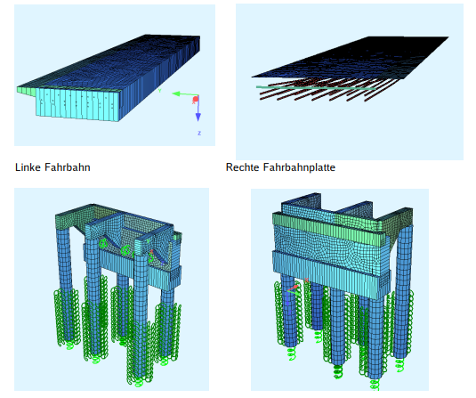
The FEM work covered the deck slabs and the piled piers as one system. Modelling the substructure alongside the deck is what allows settlement sensitivity and foundation stiffness to feed back into the deck design.
Time-dependent effects need explicit treatment on a composite structure. Concrete creeps and shrinks, steel does not. Shrinkage of the slab is restrained by the girders, which puts the slab into tension and the steel into compression before any traffic load arrives. Creep gradually transfers stress from the concrete into the steel over the life of the structure. Short-term and long-term conditions give different answers, and both have to be checked.
Standards and tools
Design followed the Eurocodes as adopted in Germany, DIN EN 1990 through 1998, with DIN EN 1994 governing composite design and the fatigue provisions applying to the shear connection and the steelwork. Analysis used SOFiSTiK, Dlubal and RFEM. Steel detailing was produced in Tekla, with drawings in Nemetschek and AutoCAD.
Construction supervision followed the design, checking that the shear connection, the concreting sequence for the slab and the erection of the girders matched the assumptions the analysis was built on.
Discuss a similar project
If you have a structure that needs analysis, design, or static analysis documentation for approval, we are happy to look at it.